Project files: ATtiny-based power delay
September 6, 2016 2 Comments
As the PCBs for my next ATtiny-based designs have landed over the weekend and I am back from my holidays, now seems to be an appropriate time to post this 🙂
What is it?
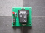
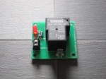
It’s my ATtiny85-based power delay controller which can be used for speaker protection etc. as described here. In addition to the controller board itself are also a couple of relay boards to do the actual signal switching. One board is stereo and based on 10A relays, the other is mono and based on a 30A relay.
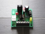
The controller board includes an on-board 5V regulator, an LED coupled directly to the ATtiny to indicate when the relay is engaged (or another purpose) and two FET-switched outputs. The last two ATtiny I/O pins can be used to trigger the chip with buttons, sensors etc. which gives tremendous versatility.
How big are the boards?
All three boards are my “industry-standard” 2”x2” (app. 51 x 51 mm.) in size, meaning they can be stacked on top of each other if needed.
What is the status of the boards?
All three boards are version 1.0 and the prototype boards looked and worked as expected.
Does it use any special/expensive/hard-to-find parts?
Nothing serious this time either 🙂
- The small heat sink for the regulator is a Fischer type SK95 with an M3 hole in the bottom, but if you’re having trouble finding this there should be plenty of other small heat sinks that will fit. In any case, the heat sink isn’t always required, it depends on your input voltage and current draw from the 5V line.
- The relays are standard types, either Omron G5LE (small board) or Omron G8P (large board). I’ve quoted Omron part numbers to give you something to go on, but there should be plenty of identical replacements from other manufacturers available.
Anything else I need to know?
- The intention is that the ATtiny chip should be programmed using the Arduino IDE. That means you need to have either a dedicated programming shield for ATtinys or wire up the chip to an Arduino board that is used as an ISP. You also need to have the ATtiny cores installed in your Arduino IDE (see explanation here) and you have to burn the Arduino bootloader onto the ATtiny yourself before filling it with the actual program.
- For programming, I highly recommend something with a ZIF-socket because it will make the whole thing much easier. I’ve got one of these on order (which recently came back in stock) because that looks brilliant, but there are shields on ebay that can be used as well. I’ve been working with this one so far and it works well, but of course you need a dedicated Arduino board to run it.
- As you can see from the schematic, the intention is that the controller board is fed from a higher voltage (9-24V) than the ATTiny requires, in order to be able to use relays that draw less current. The onboard regulator will provide the 5V that the ATtiny requires. If you are using the big mono relay boards, be aware that the worst-case power draw for these is around 1.2W each. This means that if you are using a pair of 9-12V relays here you’ll need to be sure that your power supply can handle that.
- The second output is intended as just that – a secondary switch – but since it’s connected to one of the ATtiny pins that provide a PWM-output, you could probably do something clever and use this for controlling a variable-speed fan fed from the same voltage as the relays. If anyone does that I would love to steal, ehm…. borrow your code 😀
- Although the relay boards have on-board protection diodes across the coils, there is also space for optional SMD diodes on the bottom of the controller PCB. Use these if you’re driving off-board relays etc.
- There is a sample sketch included in the download file, but please don’t laugh (too loudly) at my pitiful attempts to code – it’s just an example 🙂
Downloads:
Download design files here
Related information:
Note: Always read the “intro post” for additional important information about my designs.
Most of the complexity here is around the coding. There are tons of links available around the web for how to use ATtinys with Arduino, so I’ll not list them here. Start from the link to the official Arduino page and then do your own search from there.


Pingback: More ATtiny experiments… | theslowdiyer
Pingback: Project files: Simple power-on delay (with 555 IC) | theslowdiyer