Project files: Headphone amp dummy-load…
October 23, 2021 Leave a comment
Managed to source the last resistors this week, so I think it is about time to publish the files for this project 🙂
What is it?
A switchable dummy-load for headphone amps and preamps. There are two ranges each with 6 steps. With the specified resistances this yields load resistances from 16R – 10k and a power level of at least 3W (up to 6W in the low-range mode).
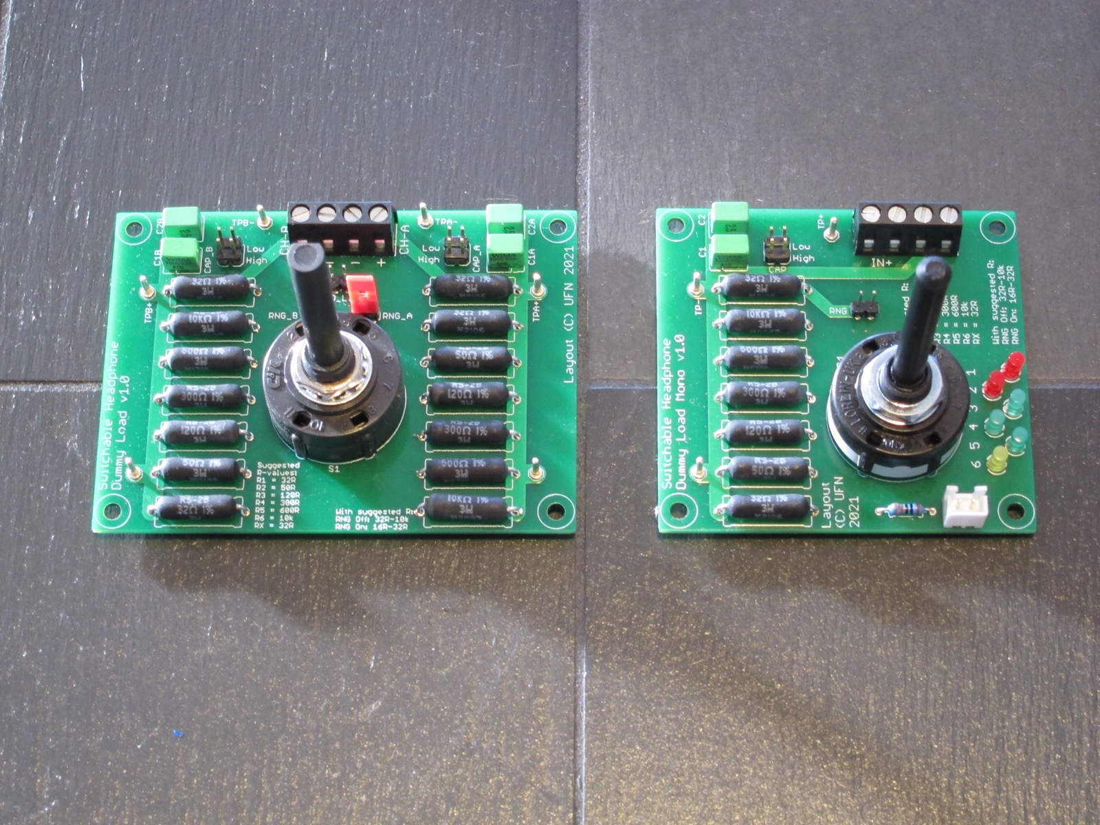
There are two board versions: One is a single stereo board with just the switch to indicate the selected range, the other is a mono version with indicator LEDs on the board so you can directly see which load is selected.
How big are the boards?
The stereo board measures 3.6” x 2.65” (app. 91 x 67 mm.) and the mono board measures 2.8” x 2.65” (app. 71 x 67 mm.)
What is the status of the boards?
Both boards are version 1.0 and they worked without issues.
Does it use any special/expensive/hard-to-find parts?
Not as such. The recommended resistors (Vishay RS02B 3W/1%) are available from Mouser and at the time of writing all in stock. Everything else apart from the load resistors should be readily available elsewhere (and of course you can use other resistors if you want to).
Anything else I need to know?
- Load capacitance: As mentioned in the original post I have included two optional positions for load capacitance. Information on what constitutes a “realistic” capacitive load for a headamp is quite hard to find, so there is some room to experiment here. I ended up with 150pF and 1.0nF but that was not just because they looked like “reasonable values” but also because I had them on hand in 2.5% tolerances (which I matched manually to get even closer to identical channels).
- Hole sizes: On both boards, the resistor hole sizes might be a little bit tight if you don’t use the specified resistors so if you want/need to buy different resistors you can check against the datasheets to ensure that what you buy actually fits. You can of course drille the holes larger if required, but in that case I’d advise you to solder the legs on both sides of the board to ensure good contact.
- Test points: On both boards there are test points which can be fitted with solder terminals as on my boards or just small pieces of wire. These points are easier to grip for a scope probe or crocodile clips on a meter if you need to take measurements as well.
- Ground link: On the stereo board, there is a jumper to connect the L/R grounds together. This would obviously be the default configuration for a headphone amp with a 3-pin TRS output, but if you want to test a “balanced” headphone amp then remember to disconnect the jumper to leave the channels independent.
- Indicator LEDs: On the mono board there is just one resistor for setting the current through all the LEDs. If you use normal red/green/yellow/orange LEDs that should be fine, but if you want to include “high-bright” LEDs as well then you can add an extra resistor on the back of the board instead of the trace connecting the switch output to the LED (rememeber to cut the trace).
- Power supply: For the mono board the voltage can be (just about) anything you like as long as you calculate the current and power dissipation in the LED resistor(s) as well. An obvious choice of PSU would be to use a small switching PSU such as an IRM-module or similar, or even a spare USB-charger.
Downloads:
Download design files here
Related information:
Note: Always read the “intro post” for additional important information about my designs.