A pair of Dynahis…

The summer is now firmly on the retreat here, and as the weather cools down and the days get shorter it also becomes more natural to stay inside and build stuff – time to dive into the project pile and finish some builds then! šŸ™‚

Read more of this post

Project files: LME49600-based headphone amp

When I built the LT1210-based preamp I thought I set a record for longest wait between making a PCB and actually trying it out. I am happy to say that the record has been broken with this – a headphone amp based on the LME49600 buffer IC, which I apparently did back in 2013 but havenā€™t managed to assemble and test until now (!).

Read more of this post

More progress…

So, here is this weekā€™s completed projects! (I honestly donā€™t think Iā€™ve ever been able to write that before, but as promised earlier I got some new rear panels so I was able to keep up the pace šŸ™‚ )

Iā€™ve manage to case and complete both the NE headphone amp and the ACP+ prototype boardsĀ and again – the time elapsed between completing the PCBs and actually being able to close the lid on the completed build has to be a new record for me šŸ™‚

For the ACP+ I have obviously made both headphone and preamp outputs despite choosing a fairly small case (and it only just fits). Now, I donā€™t think the wiring on this one is going to win me any prizes (nor, I expect, is the slightly OTT chrome-plated volume knobā€¦) but that doesnā€™t really matter now because it works well and it is undoubtedly a cracking amp – whether used as a headamp or a preamp.

For the NE-amp I only had the headphone output to worry about, but I still ended up upsizing the case a little bit because it simply looked and worked much better. Power supply is one of my filtered IRMs and that seems to work well. Again, I am a bit surprised that this old design can turn into such a well-behaved amplifier. Pretty stupid of me to wait so long to start building it šŸ˜‰

Completing the “set” we have a Whammy-amp, namely the official board I bought and showed here. This build was supposed to be one of the easiest because of the all-in-one board, but actually turned out to be one of the most annoying I have done for a while. I managed to measure up the front panel incorrectly not just once, but twice (!). First I couldn’t fit the headphone jack and having fixed that I then found I could not close the case because of the tall heat sinks. It seems complacency is indeed a dangerous enemy… Either way, it’s now done and working šŸ™‚

Project files: The NE class A headphone amp…

Iā€™ve now finished my testing on the NE class A headamp I described earlier, so here are the design files if anyone else thinks it looks like an interesting design and wants to give it a go šŸ™‚

Read more of this post

XP-7 headamp clone…

Another build Iā€™ve managed to finish during the past week is the XP7 clone (originally shown here). As I explaned originally this is more or less a standard OPA+BUF634 amplifier with the only real ā€œUSPsā€ of this implementation being the use of AD797 opamps and lower gain resistor values than usual – both of which should help reduce noise.

Iā€™ve done my bit for noise reduction as well by making the amp powered by two 9V batteries – I havenā€™t tested the battery life yet, but hopefully it isnā€™t too bad šŸ™‚

Regardless of that I donā€™t particularly need another headphone amp as I donā€™t really listen to headphones that often any more.Ā However since this one is battery powered I will not pack it too far away, because a battery powered amp is quite useful for testing (due to no ground loops). And, after a little bit of listening to the finished product I have to say that it doesn’t actually sound bad at all…

Meeting your heroesā€¦

Thereā€™s an old saying that ā€you should never meet your heroesā€, because you might be disappointed. I understand where the saying comes from, but itā€™s actually something I have been trying to do ā€“ at least meeting some of my various ā€œaudio heroesā€. There are a couple of examples here and here, and this post is another example (plus there are a few more I havenā€™t gotten to yetā€¦ šŸ˜Š ).

At first look, this is simply another discrete headphone amplifier. However, the design was published in 1985 in a Danish magazine called Ny Elektronik so it was already fairly old when I started reading about it in the mid-90ā€™es or thereabouts (the magazine itself folded in 1989…). Itā€™s one of the designs that I remember reading about and being very intrigued about even before the internet and before I started building headphone amps ā€œfor realā€.

Back then, a dedicated headphone amp was really a ā€œnicheā€ item, but as a teenager without the space or the budget for expensive speakers I had already found out that headphones were a ā€œshortcutā€ to good sound that I could not otherwise afford or use, so I had already ā€œcaught the bugā€ which then only became stronger when I found headwize and later head-fi online in 2000/2001.

I actually still have a photocopy of the original magazine article ā€“ made at my local library back when you had to buy photocopies by the page ā€“ but a few years ago someone pointed me to an online library of all these old magazines (back to the mid-70ā€™es) so I have an electronic copy as well, which is what I stumbled upon on my hard drive again a few months ago.

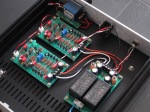
Part of the reason I never built this amp originally was that I could not make the PCB from my photocopied magazine article and also because the article mentions using low-noise (2SD737/2SB786) transistors. However, when I looked at it again more carefully I actually realized that everything I needed is still available (the low-noise transistors are an option, not a requirement) and so all that was needed was therefore a new PCB layout which wasnā€™t too much of a problem once I got started.

Apart from making the board single-channel and removing some onboard voltage regulation that I did not think was necessary Iā€™ve left the design as-is. The only change otherwise was to reduce the gain ā€“ the original gain is a poweramp-like 28.5x, which I guess makes sense if you had high-impedance headphones and a 1980ā€™es turntable as the source, but Iā€™ve dropped it down to about 5x which is much more reasonable for todayā€™s use (and honestly still a bit on the high side).

The technological development hasnā€™t been all bad though, because where the original design mostly specified 5% resistors (except the gain resistors), now 1% is pretty much standard. Iā€™ve also ā€œupratedā€ the power ratings a little bit, so where the original resistors were 1/8W and 1/4W Iā€™ve used 1/4W and 1/2W. I did some outline calculations on the dissipation and the original bias setting seems quite high, so in the interest of reliability I changed the resistors and I plan to bias the amp a bit lower.
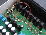
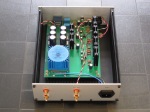
Now Iā€™ve only had time to do basic testing on this, but it powers up, biases up well, the DC-servo works as expected and it plays clean audio ā€“ so thus far I am very happy. Still need to check thermal stability and listen to it a bit more and then Iā€™ll make the files public in case anyone else wants to have a go at it.

A blast from the past…

Recently I was rummaging around one of my (many) boxes of half-finished designs looking for something else when I found this – a Sijosae Gilmore board which I never put to any use.

For those of you that havenā€™t been doing DIY for as long as I have: This is a version of the original Kevin Gilmore class A headphone amplifier modified by Korean diyā€™er Sijosae to fit a much smaller board. Sijosae was an absolute artist who made miniaturised versions of pretty much all the popular headphone-amp designs of the day while also experimenting with different topologies for buffers, rail splitters and similar circuit components. Even if he is no longer actively posting you can still see his characteristic schematics pop up in google searches and being referenced in new designs as well.

Sijosae’s version of the Gilmore amp could (theoretically at least) be squeezed into an Altoids tin like a CMoy-amp. In reality there would be noĀ space forĀ batteries and the battery life would be very short because this amp runs in class A, but at least mechanically it would fit. He also made a simplified “EZ-gilmore” version of the Gilmore circuit which I cloned as well (but also never used, now I come to think of it…)

The Gilmore design is back from the headwize-days and the final PCB layout was done by an american user called Subsonic whoĀ subsequently offered it as aĀ ā€œgroup buyā€ on Head-fi in 2003. As I recall, this was the first group buy I ever participated in and one of the firstĀ headphone amp PCBs I bought internationally – if not the first. To say this started a tradition for me is something of an understatement (ā€œavalancheā€ is more like it šŸ˜‰ )

The board has been in storage for so long I donā€™t remember exactly why it was putĀ away in the firstĀ place, but now that I have dug it out I am actually going to test it. I seem to remember it had offset-issues that I found very puzzling at the time, but I am thinking that the 15+ years of diy-experience I have added since might help me solve them this time… šŸ˜€

Project files: An unloved amp?

Well this is really “unloved” in two ways, but I thought I’d share it anyway šŸ™‚

A while ago I ws cleaning up a little and I found the boards for this amplifier based on the LT1210 IC. Despite being from 2016 I never put the design together originally (don’t remember why) so I decided “better late than never” and tried it now. And you know what – it works!

Apart from being “unloved” because it took me nearly four years to put it together and test it, this amp is also “unloved” because the LT1210 doesn’t seem to be used that much for audio applications. It is a a current feedback power opamp with a massive current capability and so it should – albeit with a few caveats – be possible to use for audio as well with good results. Also, like e.g. the AD815 the original applications for the LT1210 (ADSL line drivers and suchlike) have all but disappeared, so – again with a few caveats – it should be possible to pick these ICs up at very good prices.

Read more of this post

ACP+ clone progress…

Just a quick update because my ACP+ clone is now (very nearly) done. It took a bit longer than I had expected because of some delays getting boards and parts, and I do actually still miss one part that will hopefully turn up next week – fingers crossed.

As I did with the ā€œWhammyā€ headamp Iā€™ve taken the original ā€œall-in-oneā€ board layout of the ACP+ and turned it into a mono amplifier board and a separate PSU (and offboard volume control). Other changes include:

  • New heat sink profile (Fischer SK104 or equivalent).
  • Various footprint-changes for parts on the amplifier board.
  • Larger footprint for the initial filtering resistors in the PSU so itā€™s possible to use inductors instead.
  • Output switching (pre/headphone) directly on the board with a tiny Omron relay (these are the parts that I am still missing).

Until I get the relays I canā€™t do the last bit of testing but so far the PSU works and both amplifier channels bias correctly and play clean audio and that is always a good starting point šŸ™‚

More information (and hopefully better picturesā€¦) to follow when everything is done.

Project files: The Borbely non-hybrid headamp

To supplement the original Borbely tube hybrid headphone amplifier are here the files for the solid-state version as described previously here. Have fun!

Read more of this post