What is it?
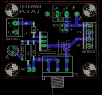
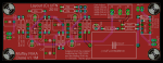
My version of the “Muffsy” RIAA board. As I observed in the first post my version really looks nothing like the original, so here’s a quick rundown of what I have changed:
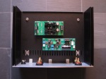
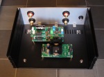
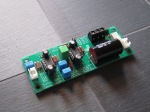
- The board is mono and intended to be stacked two channels on top of each other as shown in the pictures because that was what I needed. Side-by-side placement and/or dual-mono configurations are of course possible as well – if maybe a little less practical…
- The board uses single opamps instead of the duals on the original. This of course increases the cost a bit, but it also offers more flexibility for those that want to experiment with how different opamps change the sound (because the choice of singles is much bigger – especially after this).
- Because I’ve found myself using the mute button on my amplifier quite a lot when changing records, I got the idea to include a relay-based mute on the output of the RIAA so that mute is available even if your amplifier doesn’t have a mute option.
- The input cap position has been kept because my usual cartridge expects a slightly higher load capacitance so I need a capacitor in that position (you can of course still leave it out if you want).
- The output cap position is bigger to make space for a more “audiophile” sized capacitor 🙂
- The selectable input impedance resistors have been removed. All of the cartridges I am reasonably going to use on my Pro-Ject turntable will be MM-types that need a 47k load impedance so I skipped this option – not that it’s a bad idea though.
- The selectable gain I have kept, but instead of a DIP-switch I used a header/jumper which doesn’t take up as much space on the board. It’s only marginally less user-friendly than the DIP-switch in my opinion.
- Otherwise the basic schematic and the component values remain the same as the original Muffsy.
How big are the boards?
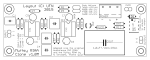
The board measures 3.925” x 1.45” (app. 100 x 37 mm.).
What is the status of the boards?
The board file is v1.1 as I’ve fixed some minor niggles with the prototypes. I’ve tested the board and it works but I still don’t have detailed listening impressions, not least because – as the pictures show – I’m missing a couple of fairly important PSU components 😉
Does it use any special/expensive/hard-to-find parts?
Most of these components are standard sizes and it should be easy to find from the usual sources, however note the following:
- Capacitors in the signal path should be polypropylene** film types and ideally 2% tolerance or less and in packages with 5mm pin spacing. If you can’t find 2% capacitors, buy a few 5% types of each value and match them using a multimeter to at least keep the variance between channels as low as possible (honestly this is worth checking regardless of what you buy).
- Resistors should be 1% tolerance (or better – so if you want to “splurge” on 0.1% types go right ahead 😀 ). Obviously the resistors for the relay and the LED are exempted from this requirement 🙂
- The muting relay is a tiny G6K type from Omron and as far as I know there are no substitutes from other manufacturers. Make sure you get the version with even 0.1” pin spacing.
- I don’t really recommend buying expensive opamps from eBay or aliexpress because it is simply too easy to fake the markings on a standard DIP-package to make a surplus TL071 look like a NOS OPA627 at 10-20 times the price, but only you can decide if you think the risk is worth taking. There are some great offers on eBay, but sometimes you have to go through quite a bit of grief to find them…
- **No, in actual fact no one is really going to die because you use polyester film caps but you’re an audiophile so you should aim for the best (within reason, if you happen to be both an audiophile and an engineer or just an audiophile that still has a bit of common sense left 😀 )
Anything else I need to know?
- The muting relay is powered by the positive supply rail (via a resistor if the voltage is higher than 12V) with the switch in series, so any latching switch will be usable as the mute switch.
- As standard, the muting relay switches both signal and ground. Not sure if this is always a good idea, but if not then it’s quite easy to bridge the GND-connection on the back of the board so only the signal is switched.
- If you don’t want the mute option at all just bridge both of the positions marked on the back the board and you can skip the relay, the resistor, the diode across the relay and of course the connector and switch.
- As is my custom for PCB layouts this is quite tight (ok, make that “cramped”), so a couple of tips: 1) remember the decoupling caps on top and 2) measure the voltage on the opamp sockets to ensure that everything is OK before mounting the opamps becasuse the decoupling electrolytics make it a bit difficult to remove the IC afterwards. If you want to experiment with different opamps, consider stacking two sockets on top of each other. This should lift the actual opamp above the electrolytics making it easier to remove.
- Again: Note the two SMD decoupling caps on the top of the board. They need to be mounted before you solder the opamp sockets!!. They also mean that you have to use a socket and you can’t mount the opamp directly to the board.
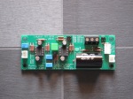
- I’ve used a basic LM317/LM337 power supply for mine (this one to be specific), but there might be something to gain by using more sophisticated low-noise types. It is also possible to power the circuit from a couple of 12V SLA batteries, but if it is worth the trouble I’m not sure (probably not though – if you want to put that much effort into a RIAA you should maybe consider starting from a more advanced circuit instead 😀 ).
- Regarding the opamps, the “default” option is the LME49710, but there are lots of other DIP-options as well that could potentially be used (LT1363, LT1028, AD797, OPA627 etc. are all common choices for RIAA-circuits) as well as of course several others in SO-8 packages that can be used with suitable adapters. Unless you already have a favourite IC, my advice would be to start from the default (which should be among the best “value-for-money” options anyway) and then change once you’ve tried it so you can more easily identify changes.
Downloads:
Download design files here
Related information:
As this is effectively a clone of the Muffsy board, you should read the Muffsy website for additional information (and if you really want the background, the original Audiokarma CNC thread as well).
Note: Always read the “intro post” for additional important information about my designs.
Oh, and remember I did this because I wanted to experiment and tailor an existing design to my own requirements and preferences. If you just want to build a board and get sound out of it, don’t bother with this but buy boards/kits of the original Muffsy instead 😀